

Brake Beam Fatigue Test Cycle Machine
Role: Mechanical Design Engineer
Organization: Cardwell Westinghouse (Wabtec Company)
Objective: Develop a high-cycle fatigue test machine capable of simulating up to 1,000,000 operational cycles on railroad brake beam assemblies under real-world load conditions.
During my time at Cardwell Westinghouse, I led the mechanical design, FEA validation, and fabrication coordination of a full-scale Brake Beam Fatigue Test Cycle Machine. The goal was to design a precision system that could apply repeatable, controlled forces representative of actual railcar braking operations, enabling long-term fatigue testing and life-cycle verification of heavy cast-steel brake beams.
The project required combining mechanical design principles, structural analysis, and hands-on manufacturing integration to produce a machine that was both extremely rigid and modular, while capable of sustaining millions of high-load cycles without structural degradation or misalignment.
System Design and Structure
The machine consisted of a multi-bay steel base frame supporting two opposing reaction stations, each equipped with high-strength machined fixtures that precisely located the brake beam under test. The structure was fabricated using A36 and A572 structural steel with Grade 8 bolting throughout, designed for easy disassembly and reconfiguration.
Key design features included:
Dual reaction arms with high-load hydraulic actuators capable of producing cyclic forces representative of real-world braking events.
Linear motion guide systems ensuring alignment of the moving fixtures under high stress conditions.
Heavy-duty precision-machined clamping blocks and V-seats for the beam pivots, maintaining geometric consistency over the entire fatigue cycle duration.
Central load transfer mechanism driven by a servo-controlled hydraulic cylinder with adjustable stroke and frequency control.
Custom fixturing plates to accommodate different brake beam geometries, allowing interchangeability for testing multiple product configurations.
The entire system was designed for modularity, allowing for simplified maintenance and future adaptability to various fatigue test setups.
Design and Validation Using SolidWorks and FEA
All mechanical assemblies were developed in SolidWorks, from initial concept sketches to detailed assembly-level CAD. The final design incorporated over 300 individual machined and fabricated components, each fully modeled and tolerance-analyzed to ensure manufacturability and alignment.
I performed extensive Finite Element Analysis (FEA) using SolidWorks Simulation, focusing on critical load-bearing members such as the base frame, actuator mounts, and reaction brackets. Analyses included:
Static load distribution and stress concentration mapping under maximum cyclic loads.
Modal analysis to avoid resonance frequencies that could amplify cyclic fatigue stresses.
Fatigue life estimation for bolted joints and weldments using endurance limit calculations.
Deflection control analysis, ensuring total displacement remained below 0.005” under peak loading conditions.
These results informed key structural refinements, such as increasing gusset reinforcement, optimizing load paths through the base rails, and stiffening the fixture interfaces to minimize deformation across the machine’s length.
Fabrication and Assembly Coordination
Once the design was finalized, I worked closely with in-house machinists and fabrication technicians to translate the 3D models into detailed 2D production drawings with full GD&T specifications. I regularly collaborated on the shop floor during the machining and assembly stages to verify tolerances, inspect machined surfaces, and oversee critical fits such as:
Bearing and pin interfaces within the actuator linkages.
Precision rail alignment for the moving slide tables.
Flatness and parallelism across bolted assemblies to ensure uniform load transfer.
I also participated in the initial machine assembly and alignment process, confirming the geometric integrity of the setup prior to hydraulic integration. Working side-by-side with machinists provided invaluable feedback that led to on-the-fly design improvements and optimized the manufacturability of complex assemblies.
Testing and Performance
Once assembled, the fatigue test system underwent multiple dry-run evaluations before full hydraulic load testing. The hydraulic actuation system was tuned to produce repeatable sinusoidal loading at controlled frequencies to simulate brake application forces.
The test machine successfully achieved the design goal of operating continuously through 1,000,000 fatigue cycles, maintaining alignment and performance consistency throughout the test duration. The system’s robust design minimized vibration and ensured that the applied stress profiles remained accurate to specification, validating the design approach and the accuracy of the FEA predictions.
Technical Impact and Legacy
This machine became a core testing asset for Cardwell Westinghouse’s R&D department, providing an industry-grade validation platform for fatigue testing of new brake beam designs and materials. Its modular and overbuilt construction ensured long-term reliability and adaptability for future research projects.
This project solidified my foundation in heavy mechanical design, finite element analysis, and manufacturing collaboration, while reinforcing my ability to deliver production-scale test systems that combine precision, reliability, and maintainability.

Brake Beam Test Cycle Machine (CAD)

Brake Beam Test Cycle Machine (Fabricated)
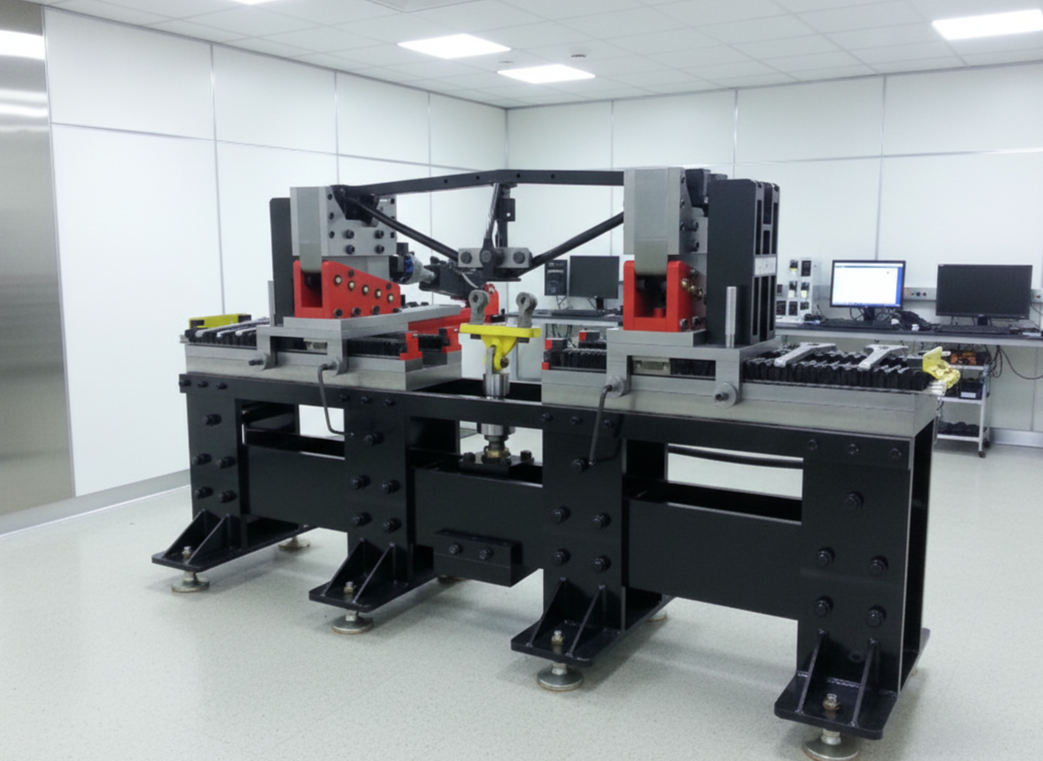
Brake Beam Test Cycle Machine
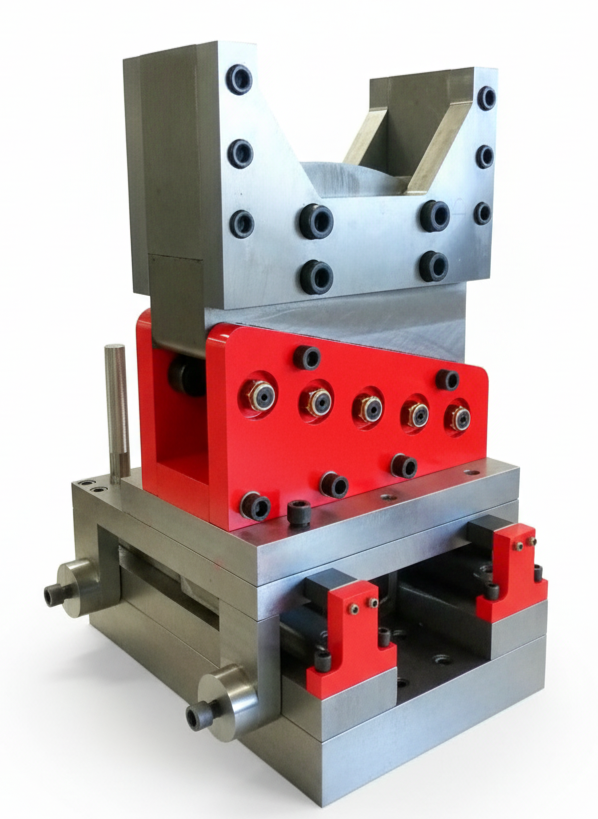
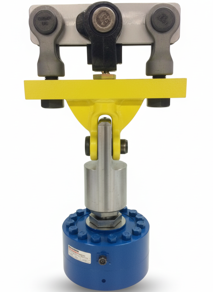
Test Cycle Machine Components