
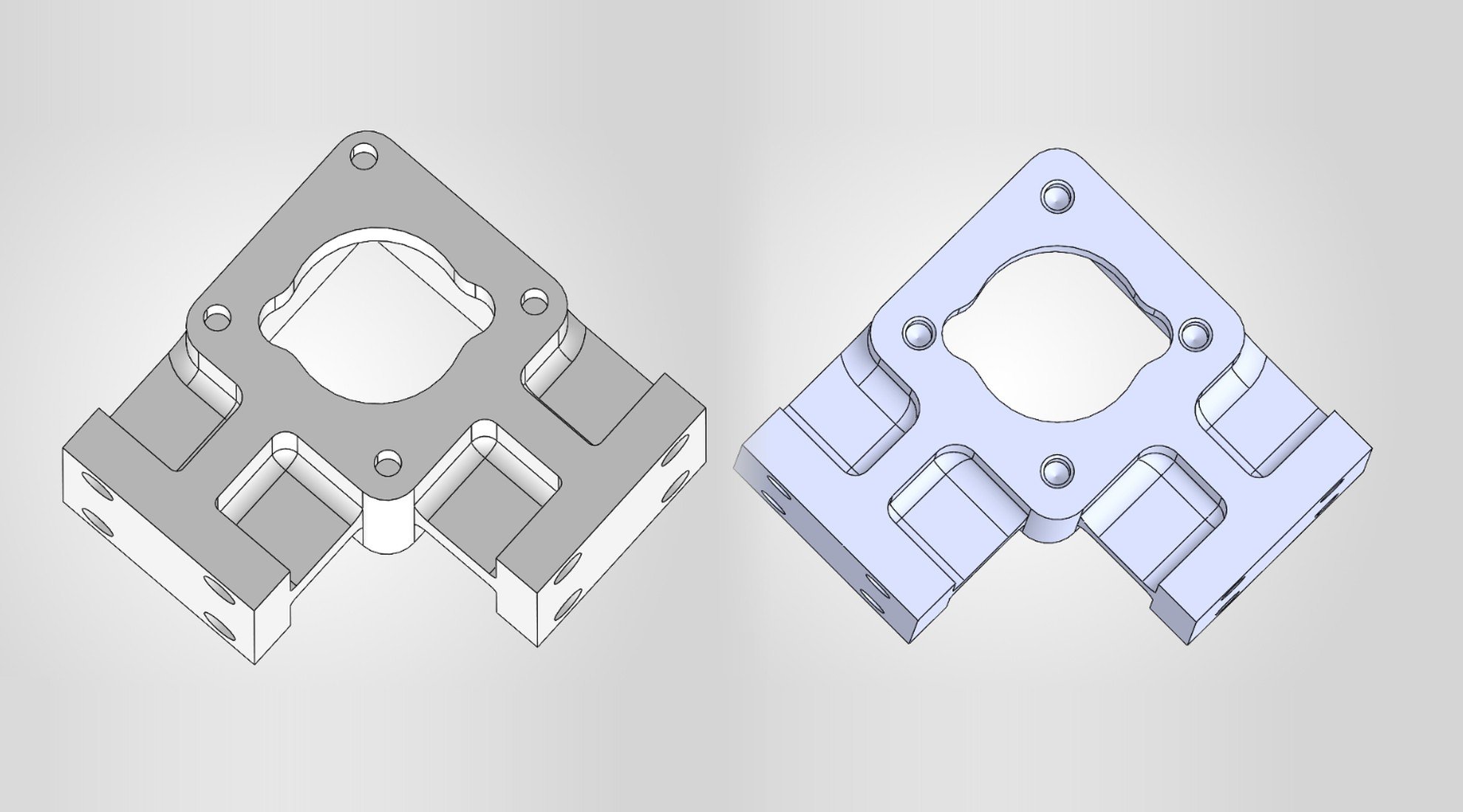
Modular Chassis Connection Nodes
Objective: Engineer the structural nodes that join stacked steel building modules, and compare cast and fabricated alternatives with the analysis and drawings needed to build them.

Client: MODS, volumetric modular construction (Laval, Québec)
Role: Lead Engineer, Structural Systems (Bedatek, contract)
Scope: Connection node design, finite element analysis, facade anchor analysis, GD&T fabrication drawings, fastener specification, and code documentation
Tools: SolidWorks, SolidWorks Simulation, ASME Y14.5 GD&T
Overview: MODS builds multi-storey buildings from steel-framed volumetric modules that are made in a factory and stacked on site. Wherever module corners meet, a structural node carries gravity, wind, and seismic loads from floor to floor and keeps the modules aligned during erection, so a handful of parts does a great deal of work.
Bedatek leads structural engineering on the module chassis connections: designing and analyzing the nodes, comparing manufacturing routes, and producing the drawings and reports that fabricators, foundries, and the engineering team work from.
Early cast ceiling node concept in SolidWorks (top) and its plan view with the bolt pattern dimensioned (bottom)
The Challenge
The baseline node is a steel casting: strong and compact, but tied to foundry tooling and lead times. MODS needed to know whether machined or welded alternatives could match it structurally, what each option would weigh, and how each would be built and inspected, all within Canadian code requirements for factory-built construction.
Node Design & Alternatives
Bedatek developed and compared several node families against the cast baseline:
Cast node baseline in ASTM A958 cast steel, the reference for strength and stiffness
Welded core assemblies built from HSS and high-strength ASTM A514 plate, with alloy insert options
Six-piece welded nodes assembled from thick structural plate
Wrought substitutes in ASTM A434 4140 alloy steel for machined-from-bar production
Each option was compared on structural performance, weight, and manufacturability, so the team could choose with the trade-offs in view.
Finite Element Analysis
Stacked two-node assemblies were modeled in SolidWorks Simulation with bolted connections and load sets supplied by the structural team, run separately for gravity, seismic tension and compression, end-plate shear, and moment in both directions. Material studies compared candidate plate and insert grades, and a separate study analyzed the facade anchor-to-chassis connections under wind suction, gravity, and seismic loading.
Drawings & Specifications
Bedatek produced fabrication drawings for nodes, welded cores, and connection plates with GD&T to ASME Y14.5, worked through reviewer markup cycles with documented dispositions, and specified ASTM F3125 Grade A490 high-strength bolting, tapped-hole callouts, and material certification notes for foundry and shop use.
Code Path
The work is framed for the Québec Construction Code (NBC 2020), with steel design to CSA S16, welding to CSA W59, and factory certification of modular construction under CSA A277.
Results
Fabricated alternatives evaluated against the cast baseline under the same load set, with plate sizes refined until they performed comparably
Weight comparison across every node version to inform cost, handling, and the final selection
Fabrication-ready drawing sets revised through formal markup cycles with change logs
Facade anchor connections analyzed and reported for the governing wind, gravity, and seismic cases
Formal FEA reports that give MODS a clear, repeatable basis for design decisions